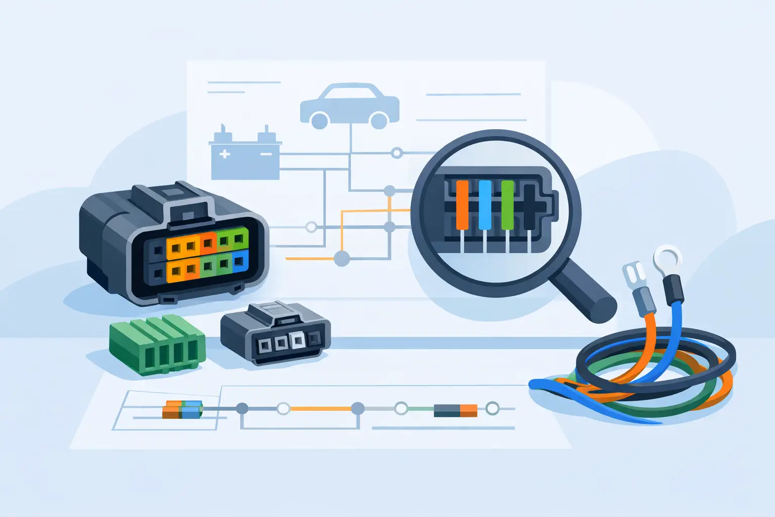
How to Use Wiring Diagram Connector Pinouts
A lot of electrical problems get harder the moment you test the wrong wire. That is usually where people lose time – not because the circuit is complex, but because they do not know how to use wiring diagram connector pinouts correctly. If you can read the connector view, identify the cavity number, and match it to the wire color and circuit function, your testing gets faster and a lot more accurate.
This matters whether you are chasing a no-start, a dead window switch, a blown fuse, or an aftermarket install. Connector pinouts turn a wiring diagram from a general map into a usable test plan. Instead of probing random wires and hoping for a result, you know exactly where power, ground, signal, and communication lines should be.
What connector pinouts actually tell you
A wiring diagram shows how a circuit is supposed to be connected. A connector pinout tells you how that information is physically arranged at the plug. That includes the connector ID, terminal numbers, wire colors, and what each terminal does.
For example, a diagram might show that terminal 3 at a headlight switch connector is battery feed, terminal 7 is ground, and terminal 5 is the output to the parking lamps. Without the pinout, you know the circuit exists. With the pinout, you know exactly where to put your meter lead.
That sounds basic, but this is where many bad calls happen. Two wires may look similar at the harness. The connector may have more than one row. Wire colors may fade, or a previous repair may have changed them. The pinout gives you a fixed reference point when visual inspection is not enough.
How to use wiring diagram connector pinouts on the vehicle
Start by matching the diagram to the exact year, make, model, and component. That step is not optional. Mid-year changes, trim differences, engine options, and body style changes can all affect connector layouts. A pinout that is correct for one version of the vehicle can be wrong for another.
Once you have the right diagram, identify the connector name or number shown for the component you are testing. You may see labels such as C101, X2, J3, or a manufacturer-specific format. Then look for the connector face view. This shows terminal positions as they appear from either the wire side or terminal side.
That last part matters. If you read a terminal-side view while looking at the back of the connector, left and right can reverse. That is one of the easiest ways to misidentify a pin. Always confirm whether the drawing is showing the front of the connector, the back of the connector, or the harness side.
After that, locate the cavity number. Most connectors have tiny molded numbers, letters, or row markings. You may need a flashlight and a pick to see them. Once you find the cavity, confirm the wire color listed on the diagram. If the pinout says cavity 4 is a yellow wire with a black stripe, and the connector shows that same wire in that position, you are on the right track.
Now test with purpose. If the pinout says a terminal should have battery voltage with the key on, check for that condition. If it should be a ground, voltage drop it under load instead of relying only on continuity. If it is a signal wire, compare live readings to the circuit function. The pinout is not just for wire ID – it tells you what normal should look like.
Reading connector views without getting turned around
The most common mistake is treating every connector image the same. They are not the same. Some diagrams show the mating face of the connector. Others show the harness side. Some use a flat 2D view even though the actual connector is angled or stacked.
If a connector has two rows, do not assume the top row starts at pin 1 and the bottom row continues in a straight line. Manufacturers number connectors in different patterns. Some go left to right, then top to bottom. Others alternate by row. The diagram will tell you, but only if you stop and read the layout instead of guessing.
Connector keyways, latch positions, and cavity blanks help too. If one corner is missing a cavity or there is a locking tab on one side, use that feature to orient yourself before testing. A lot of wrong-pin checks happen because someone rotated the connector in their head.
Why pinouts save time in real diagnostics
When a circuit fails, the problem is usually one of a few things: missing power, bad ground, open wire, short to ground, short to power, failed module, or failed component. Connector pinouts help you separate those possibilities fast.
Say a fuel pump does not run. The diagram may show power from a relay, a ground at the frame, and a control circuit from the module. The connector pinout lets you check each terminal directly at the pump connector and upstream connectors. If power and ground are present at the correct pins during command, the pump is likely bad. If power is missing, you move backward through the circuit using the same pin references.
That is faster than replacing parts or tearing open harness tape without a plan. It also prevents false failures. A component can test bad only because the feed or ground was never verified at the right cavity.
Use wiring diagram connector pinouts for installs too
Pinouts are just as useful for adding equipment as they are for diagnostics. If you are installing a remote start, trailer brake controller, backup camera, aftermarket lighting, or audio equipment, you need to know which wires actually carry the functions you want.
This is where guesswork causes expensive damage. Tapping the wrong wire can disable a module, pop a fuse, or create a communication fault. Modern vehicles pack multiple circuits into one connector, and not all of them are safe to use as a trigger or power source.
A good pinout helps you identify switched power, constant power, illumination, reverse signal, CAN lines, speaker outputs, and grounds correctly. It also helps you avoid low-voltage reference circuits and data lines that should never be probed aggressively or loaded with accessories.
When the wire color does not match
Wire color is useful, but it should not be your only reference. Age, dirt, heat, fading, and prior repairs can all make color identification unreliable. On some vehicles, similar shades are hard to distinguish under shop lighting. On others, stripe colors are so thin they disappear under grime.
That is why cavity location comes first. Use the connector shape, cavity number, and function together. If the wire color seems off but the cavity and circuit behavior match, you may be looking at a production variation or previous repair. If the cavity and color both disagree with the diagram, stop and verify the vehicle information before going further.
What pinouts cannot tell you by themselves
A connector pinout is not a full diagnosis. It tells you where to test and what each terminal should do, but it does not explain why a signal is wrong. You still need to understand circuit operation.
For example, a module-controlled ground may only appear under certain conditions. A sensor signal may vary based on temperature, load, or key state. A communication line will not behave like a simple power wire. If you use the pinout without knowing the circuit logic, you can still make a bad call.
The trade-off is simple. Pinouts give speed and precision, but only when paired with the right vehicle-specific diagram and a basic testing method. They are a map, not a shortcut around electrical fundamentals.
Getting the right pinout the first time
Generic manuals are where a lot of confusion starts. They may cover multiple years, multiple trims, or broad system groups without enough connector detail. Forum screenshots are even worse because you often do not know what vehicle they came from or whether the image is complete.
A better approach is to pull the diagram by exact fitment and exact component. That keeps you focused on the circuit in front of you instead of sorting through pages that do not apply. Carwiringnew.com is built around that workflow – select the year, make, model, and component, then get the wiring information that matches the job.
When the connector pinout matches the vehicle, your tests get cleaner, your repairs move faster, and you spend less time second-guessing what wire you are on. The next time you are staring at a packed connector with ten similar wires, slow down, read the cavity view, and let the pinout do the sorting for you.