CAN Bus Wiring Diagram for Diagnostics
When a scan tool loses communication with half the vehicle, guessing gets expensive fast. A can bus wiring diagram for diagnostics gives you the map you need to stop chasing symptoms and start checking the network the right way.
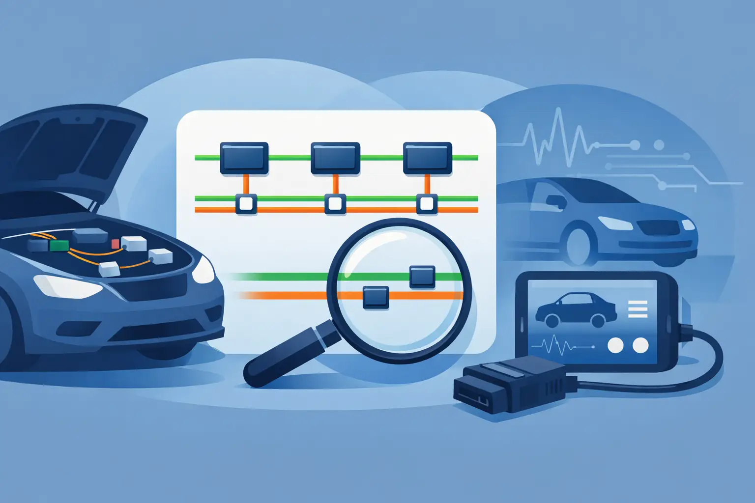
Modern vehicles depend on Controller Area Network communication to let modules share data. The PCM, ABS, airbag, body control module, instrument cluster, and other controllers are all talking on the same network or on separate subnetworks tied together through a gateway. When that network goes down, the fault can look like almost anything – no-start, dead gauges, warning lights, transmission issues, or modules that will not respond.
A wiring diagram does more than show two twisted wires. It shows where the network starts, where it branches, which modules sit on it, where power and ground are supplied, and where connectors or splices can fail. That is what makes it useful for actual diagnostic work.
What a CAN bus wiring diagram for diagnostics should show
For network testing, a useful diagram needs more than wire color and pin numbers. You want the full path of CAN High and CAN Low, the module layout, splice packs if equipped, gateway modules, diagnostic connector pins, termination points, and the power and ground feeds for each module on that branch.
That last part matters. A module with no power or bad ground can pull down the network and make it look like a communication problem when the root cause is a basic feed issue. If your diagram only shows the communication lines, you may miss the reason the bus is failing.
Some vehicles use one high-speed CAN line. Others use multiple buses, such as high-speed CAN for powertrain and a separate low-speed or body CAN for convenience systems. Many newer platforms also use gateways to connect those networks. If you are testing the wrong bus, your readings may look normal while the actual fault sits elsewhere.
Start with the complaint, then match it to the network
Before touching a meter, look at what is and is not working. If the engine starts but the power windows, radio, cluster functions, and HVAC controls are dead or acting erratic, you may be looking at a body network issue. If the vehicle will not start and the scan tool cannot see the PCM or TCM, focus on the high-speed side first.
This is where the diagram saves time. It lets you separate the affected modules from the unaffected ones. If every failed feature is tied to one branch, one connector, or one gateway, you have a direction instead of a pile of codes.
A full module scan helps, but it does not replace the diagram. Network codes often point to loss of communication with another module, not the actual wiring location. The wiring diagram gives you test access points and shows which modules share the same communication path.
The core checks that matter
Check network resistance with power off
On many high-speed CAN systems, you should see about 60 ohms across CAN High and CAN Low with the ignition off and modules asleep. That reading usually comes from two 120-ohm termination resistors in parallel. If you see 120 ohms, one termination may be missing or one side of the network may be open. If you see very low resistance, the bus may be shorted or a module may be internally failed.
That said, 60 ohms is not universal for every network on every vehicle. Some systems are configured differently, and some readings are affected by where you test. The diagram tells you whether the bus uses standard termination and where those resistors are located.
Check bus voltage with the network awake
With the key on, many high-speed CAN systems sit around 2.5 volts on both lines at rest. During communication, CAN High typically rises and CAN Low typically drops. If one line is pinned near 0 volts or battery voltage, you may have a short to ground, short to power, or a failed module dragging the line.
Again, vehicle design matters. Some low-speed networks behave differently. That is why exact fitment matters more than generic advice.
Verify powers and grounds before condemning a module
A module that is offline is not always a bad module. Check its main power feed, ignition feed if used, and ground integrity. The wiring diagram will show fuse protection, shared grounds, and connector locations. A loose ground behind the dash can take out a network branch and waste an hour of unnecessary module testing.
How to use the diagram to isolate a short or failed module
The fastest path is usually divide-and-conquer. If the entire bus is down, locate the modules on that network from the diagram and disconnect them one at a time, or isolate branches where the design allows. Watch for the resistance or voltage to return to normal.
This works best when the diagram shows splice locations and intermediate connectors. On many vehicles, the bus branches out from a splice pack or junction connector. Disconnecting one branch can tell you whether the fault is in the front harness, rear body harness, door network, or a single controller.
If unplugging one module restores communication, do not stop there. Check the connector and harness at that module for corrosion, water intrusion, pin drag, or aftermarket damage. A bad module is possible, but so is a harness issue at the same location.
If unplugging modules changes nothing, move upstream. Check the gateway, major splice points, and the diagnostic connector path. If the scan tool cannot communicate at all, verify that the diagnostic link connector has proper power, ground, and the expected communication pins tied into the network shown on the diagram.
Common mistakes when reading a CAN bus wiring diagram
One common mistake is treating every twisted pair as the same network. Vehicles can have multiple twisted pairs, different bus speeds, and private communication lines between only a few modules. Wire color alone is not enough. Follow connector numbers, splice labels, and module names exactly.
Another mistake is ignoring shared grounds and fuse feeds. If several modules on one branch lose ignition power from a common fuse, they may all set communication codes even though the network wiring is intact.
A third mistake is testing at the easiest connector instead of the right connector. A reading at the OBD-II port is useful, but it is not the whole story. If the fault sits beyond a gateway or on a separate body bus, the DLC may not tell you much. The diagram shows where to move next.
Aftermarket accessories also complicate bus faults. Remote starts, alarms, radios, GPS trackers, and lighting kits are common sources of tapped wires, poor grounds, and damaged insulation. If the vehicle has add-ons, compare the harness routing to the diagram and inspect any area where someone may have tied into ignition, data, or body control wiring.
Why exact vehicle fitment matters
A CAN layout can change within the same model line. Trim level, engine, drivetrain, safety package, and production date can all affect module count, gateway design, splice locations, and connector pinouts. Using the wrong diagram can send you to the wrong wire, the wrong module, or the wrong expected reading.
That is why a vehicle-specific wiring diagram matters more on network diagnostics than on many basic circuits. With lighting or horn circuits, a generic layout may still get you close. With CAN, close is not good enough. You need the exact year, make, model, and the system you are testing.
If you are troubleshooting a communication issue, start with the correct diagram for that exact vehicle and component group. Carwiringnew.com is built around that workflow, so you can select the vehicle, pull the right diagram, and get to testing instead of sorting through broad manuals.
CAN bus wiring diagram for diagnostics in the real world
Most network faults are not dramatic. They are usually a rubbed harness near a bracket, corrosion in a floor connector, a water-damaged module, a weak ground, or one controller pulling the bus down. The challenge is not understanding what CAN does. The challenge is finding the exact place where communication stops behaving normally.
That is why the diagram matters. It turns a vague communication complaint into a sequence of checks. Identify the network. Verify resistance and voltage. Check powers and grounds. Isolate branches. Disconnect modules with a plan. Confirm the fault before replacing parts.
If the readings do not match the expected pattern, do not force the diagnosis. Step back and verify that you are on the correct bus, using the correct pinout, on the correct vehicle configuration. A few minutes spent confirming the diagram usually saves a lot more than that at the bench or in the bay.
When the network is the problem, speed comes from accuracy, not shortcuts. The right wiring diagram gives you both.