How to Test Relay Wiring the Right Way
A relay can make a simple problem look bigger than it is. You turn the key, hit the switch, or command a circuit on, and nothing happens. Before replacing parts, learn how to test relay wiring in a way that separates a bad relay from a bad feed, weak ground, failed control signal, or open load side.
Most automotive relays are simple once you break them into two circuits. One side is the control circuit, usually the coil that gets power and ground to energize the relay. The other side is the switched circuit, where battery power is passed to the component when the relay closes. If you test both sides in order, the fault usually shows up quickly.
How to test relay wiring without guessing
Start with the relay removed and the circuit identified. If you do not know which cavity is power feed, ground, control, or output, stop there and get the correct wiring diagram for the exact year, make, model, and component. Relay terminal layouts are often similar, but wire colors, pin assignments, and control strategy can vary by vehicle.
On a typical 4-pin relay, terminals 85 and 86 are the coil side, and 30 and 87 are the switched side. On a 5-pin relay, you may also have terminal 87a, which is the normally closed contact. That matters because a circuit can have continuity when the relay is off and lose it when energized, depending on design.
Before meter testing, do a quick visual check. Look for overheated terminals, spread female pins in the socket, corrosion, melted plastic, aftermarket taps, or repairs near the relay box. A relay may be fine while the socket underneath is heat-damaged and dropping voltage under load.
What you need before testing
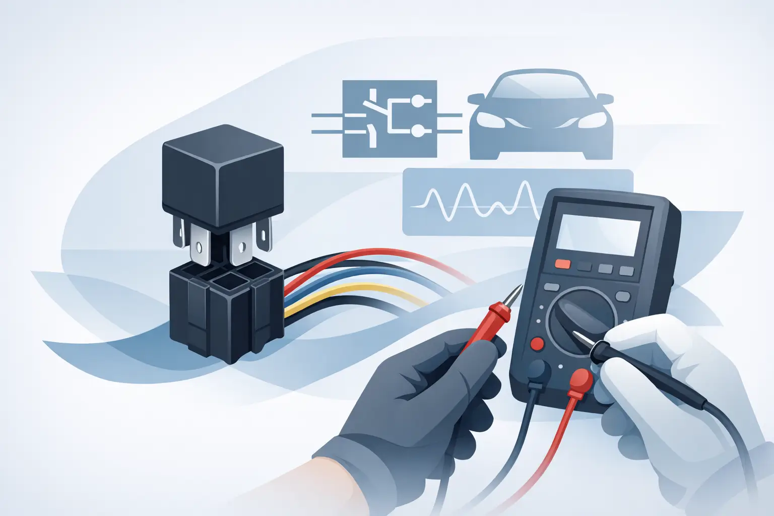
A digital multimeter is enough for most relay wiring checks. A test light is also useful because it puts a small load on the circuit and can expose weak power or ground that a high-impedance meter may miss. If the circuit is computer-controlled, use care with jumper wires and avoid forcing voltage into a control wire unless the wiring diagram confirms it is safe.
A fused jumper wire can help when you want to bypass the relay briefly to test the load side. That said, bypass testing is not the first step. It is a confirmation step after you know which cavity does what.
Identify the four things that matter
When you test relay wiring, you are really checking four conditions. The relay needs constant or switched power at the feed side, a usable path to the load, power or ground on one side of the coil, and the matching control signal on the other side of the coil. If any one of those is missing, the relay will not do its job.
Some vehicles switch power to the coil. Others switch ground through a control module. That is why the wiring diagram matters. If you assume the module is sending power when it is actually providing ground, the readings will make no sense.
Step 1: Check relay feed power
With the relay removed, backprobe or probe the relay socket and find the terminal that should have battery voltage. This is often terminal 30. Key position matters on some circuits. A cooling fan relay may have battery voltage all the time, while an accessory relay may only be live with the key on.
If battery voltage is missing, the relay is not your first problem. Check the upstream fuse, fusible link, bus bar, or power distribution center feed. If voltage is present but lower than expected, especially under load, suspect corrosion, heat damage, or a poor connection at the fuse box.
Step 2: Check the load side of the circuit
Next, identify the terminal that leaves the relay and goes to the component, often terminal 87. With the relay removed, that terminal should not usually show battery voltage unless the circuit is backfeeding through the load or you are working with a normally closed setup.
What you want to know here is whether the wire from the relay to the component is intact. Depending on the component, you may check continuity with the battery disconnected or verify operation by using a fused jumper from the feed terminal to the load terminal. If the component runs when jumped, the load side is usually good, and the problem is likely in relay control.
Use judgment here. Jumping a high-current circuit without knowing the current draw or circuit condition can create a bigger problem. For motors or fuel pumps, a fused jumper is the safer move.
Step 3: Test the relay coil power and ground
Now move to the control side, usually terminals 85 and 86. One side of the coil should receive power or ground when the circuit is commanded on. The other side should receive the opposite. On older circuits, a switch may control the relay directly. On newer vehicles, a body, engine, or lighting control module may handle it.
With the command active, check one coil terminal for voltage and the other for ground. If both are present, the relay should click and switch. If one is missing, trace that side of the circuit.
A quick example helps. If one coil terminal has 12 volts all the time and the other never goes to ground when the switch is pressed, the relay itself may be fine. The missing piece could be a bad switch input to the module, a failed module driver, an open wire, or a missing ground path.
Step 4: Verify voltage drop, not just voltage presence
This is where many relay tests go wrong. Seeing 12 volts on a meter does not always mean the circuit can carry current. A corroded terminal may show battery voltage with no load but collapse when the relay energizes.
If the relay clicks but the component does not work, check voltage drop across the feed side and the ground side while the circuit is loaded. High voltage drop points to resistance in the wiring, terminal fit, splice, or ground connection. This is especially common in underhood fuse boxes and older lighting circuits.
How to test the relay itself
Once the wiring checks are in progress, test the relay too. Measure resistance across the coil terminals. Many automotive relays will show some resistance, not open and not dead short. Exact values vary, so this is more of a basic pass-fail check than a final judgment.
Then apply power and ground directly to the coil using jumper wires, if safe for the relay type. You should hear or feel a click. At that point, check continuity across the switched terminals. With the coil de-energized, 30 to 87 should usually be open on a standard normally open relay. Energized, it should close.
This test only proves whether the relay can switch on the bench. It does not prove the vehicle socket is supplying the right inputs. A good relay can still fail in service if the socket has poor terminal tension or low voltage under load.
Common relay wiring faults
When a relay circuit fails, the relay is often blamed first because it is easy to replace. In practice, wiring and terminal faults show up just as often. Burned sockets are common on blower motor, cooling fan, and headlamp circuits because heat builds up over time. Ground-side control faults are also common on module-controlled systems.
Water intrusion changes the picture. If the relay box or underhood fuse center has taken on moisture, expect corrosion inside the socket, green copper in the harness, and intermittent voltage drop. In that case, replacing the relay alone will not last.
Aftermarket wiring can complicate testing too. Alarm systems, remote starts, light bars, and trailer wiring often introduce splices or taps into relay-controlled circuits. If the factory diagram says one thing and the harness shows another, inspect for non-factory changes before chasing a module fault.
When the wiring diagram becomes the real fix
If your readings do not match the expected relay behavior, the fastest move is not more guessing. It is getting the exact diagram for the exact vehicle and component. Relay cavity positions, splice locations, shared grounds, fuse names, and module pinouts differ even within the same model line.
That is where a vehicle-specific diagram saves time. A generic relay test tells you the method. The right diagram tells you where to put the meter and what should be there. For a DIYer, that can mean finishing the repair without replacing good parts. For a shop, it means less stall time and a cleaner diagnosis.
If you use Carwiringnew.com, start with the vehicle details and component you are working on so you are testing the correct relay path, not a similar one from a different trim or engine package.
A practical way to think through the fault
If the relay never clicks, look at the coil side first. If it clicks but the component stays off, look at the feed side, output side, and voltage drop under load. If jumping the load side runs the component, the output path is likely fine and the control side needs attention. If the relay tests good on the bench but fails in the vehicle, inspect the socket and loaded voltage at the socket, not just the relay.
That sequence keeps the job tight. Test for feed, test for output path, test coil command, then test voltage drop. Most relay wiring faults show up before you get far.
The best closing move on any relay problem is simple: trust the meter, trust the diagram, and do not let one click from a relay fool you into thinking the wiring is good.