How to Test Continuity With Wiring Diagram
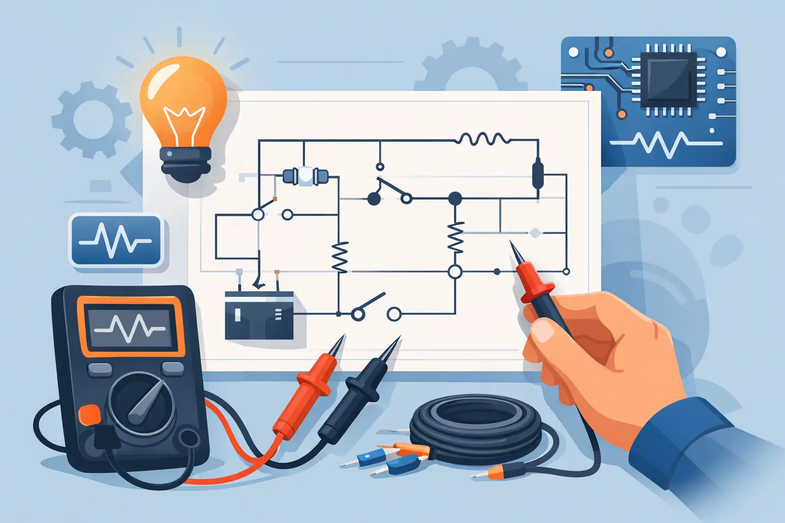
If your meter shows OL and the part still looks fine, you do not have a parts problem yet – you have a circuit path problem. That is where knowing how to test continuity with wiring diagram detail matters. A continuity test is not just checking whether a wire is good. It is checking whether the exact path shown on the diagram still exists in the vehicle.
A lot of wasted time comes from testing wires without first identifying the full circuit route. On modern vehicles, that route may pass through a splice, connector, switch, module, or ground point before it ever reaches the load. If you skip the diagram and probe at random, you can easily condemn a good harness or miss the real open.
What continuity testing actually tells you
Continuity means there is an unbroken electrical path between two points. On a multimeter, that usually shows as a beep or very low resistance. In automotive work, that can confirm a wire is intact from one end to the other, or that a switch closes when it should.
What it does not tell you by itself is whether the circuit works correctly under load. A corroded wire can still beep for continuity and fail when current demand rises. So continuity testing is best used to find hard opens, broken wires, bad terminals, and failed switch contacts. For voltage drop, high resistance, or weak grounds, you need additional testing.
Before you test continuity with a wiring diagram
Start with the exact diagram for the exact vehicle, engine, trim level, and component. That part matters more than many people think. Wire color, connector pinout, splice location, and even circuit strategy can change between model years or options.
Read the diagram all the way through before touching the meter. Identify the power source, fuse, switch or control side, load, connector numbers, splice points, and ground. Then decide what exact segment you are testing. That keeps the job controlled. You are not testing a whole mystery circuit. You are testing one known path from point A to point B.
Always depower the circuit before checking continuity. Remove the fuse, disconnect the battery if needed, and isolate the section you are testing. Never check continuity on a live circuit. At best, the reading is false. At worst, you damage the meter.
How to read the wiring diagram for continuity testing
The diagram gives you the map. Your job is to break that map into testable sections.
Look first at the component you are diagnosing. If it is inoperative, find its power feed and ground path. Follow the wire labels, colors, and connector IDs. If the power side runs from Fuse F12 to Connector C203 pin 4 and then to the component, that gives you a clean test path. If the ground side goes through Splice S110 to Ground G104, that is another path to verify.
This is also where you decide whether the issue is likely an open in the wire, a bad connection, or a failed device. If the diagram shows multiple branches off one splice and only one branch has failed, you usually do not start at the fuse. You start at the branch after the splice.
Focus on one segment at a time
This is the part that speeds diagnosis. Do not test from the battery to the component unless the circuit is very simple. Instead, test between connectors, between a connector and a splice, or between a connector and ground.
If the section tests good, move to the next. If it fails, you have narrowed the fault area. That is how the diagram saves time.
How to test continuity with wiring diagram steps
Set your multimeter to continuity or the lowest ohms range. Touch the meter leads together first to confirm the meter responds properly. Some meters beep instantly, some show near-zero resistance. Know what your meter considers normal.
Next, isolate the wire or circuit segment. If possible, unplug both ends of the wire you are checking. For example, if the diagram shows a wire running from the headlamp switch connector to the body control module, disconnect both connectors. Place one lead on the identified terminal at one end and the other lead on the matching terminal at the other end.
If the meter beeps or shows very low resistance, that wire segment has continuity. If it shows OL or very high resistance, the path is open or badly damaged. Wiggle the harness while watching the meter if you suspect an intermittent break. A reading that changes when the harness moves often points to an internal break near a bend, connector, or repaired section.
Now compare that result to the rest of the diagram. If the wire itself is good, the open may be at a terminal, splice, switch, or ground point. Move your test points according to the diagram rather than guessing. For example, if continuity is good from the switch to an intermediate connector but bad from that connector to the load, your problem is downstream.
Testing grounds with the diagram
Ground faults are common, and the wiring diagram tells you where the ground path ends. If a component grounds through G302, test continuity between the component ground terminal and the actual ground point. If that path is open, inspect the ground eyelet, mounting surface, and nearby splice.
A clean beep does not always mean the ground is strong enough under load, but it does tell you the path exists. If continuity is good and the component still acts weak or unstable, follow up with a voltage drop test.
Testing switches and closed contacts
A wiring diagram also helps when a switch sits in the middle of the circuit. Instead of testing the whole path with the switch installed, use the diagram to identify the input and output terminals. Then check continuity across the switch in the ON and OFF positions.
If the diagram shows the contacts should close in one position and the meter stays open, the switch has failed or the terminal identification is wrong. That second part matters. Always verify pin numbers against the connector view if available.
Common mistakes that slow the job down
The biggest mistake is using the wrong diagram. The second is testing a powered circuit in continuity mode. After that, most errors come from not isolating the segment being tested.
Parallel paths can trick you. On a shared circuit, a meter may show continuity through another component or module even when the wire you care about is open. That is why disconnecting both ends is the cleanest method. If you cannot isolate both ends, be careful with readings that seem too good.
Another common miss is trusting wire color alone. Color helps, but connector ID and pin location matter more. Vehicle harnesses get repaired, colors fade, and options change routing.
When continuity is not enough
If the wire tests good but the circuit still fails in operation, stop chasing continuity alone. A wire can pass a low-current ohms test and still fail under load due to corrosion, heat damage, or partial strand breakage.
That is where the wiring diagram still helps. Use it to identify where to perform voltage checks and voltage drop tests across the same path. Continuity finds opens. Voltage drop finds resistance that continuity mode may miss.
Getting faster results from the right diagram
The practical value of continuity testing is not the meter beep. It is knowing exactly where to place the probes. That comes from a correct vehicle-specific diagram, not a generic manual or a forum screenshot.
If you are tracing an open on a lighting circuit, no-start issue, power window feed, or accessory install, the right diagram cuts out the guesswork. At Carwiringnew.com, the search starts by year, make, model, and component so you can pull the exact circuit you need instead of sorting through unrelated pages.
When the diagram matches the vehicle, continuity testing becomes a short process. Identify the path. Isolate the section. Probe the correct terminals. Move to the next segment only if the last one passes. That is how you find opens without replacing good parts or tearing apart the wrong section of harness.
The best closing rule is simple: do not ask the meter to find the fault before the diagram tells you where the fault can be.