Guide to Relay and Fuse Box Diagrams
A blown fuse should be a quick check, but it turns into wasted time when the box cover is missing, the legend is unclear, or the diagram you found does not match the vehicle in front of you. That is where a proper guide to relay and fuse box diagrams helps. If you are tracking down a no-start, dead blower motor, inoperative headlights, or a parasitic draw, the diagram is what keeps the job moving.
What relay and fuse box diagrams actually tell you
A fuse box diagram is more than a map of slot numbers. It shows which circuits are protected, how power is distributed, and where relays sit in the system. On many vehicles, that includes more than one panel – an underhood power distribution box, an interior fuse panel, and sometimes a rear or trunk-mounted box.
The key detail is fitment. Fuse and relay assignments can change between trims, engines, body styles, and production dates. Two vehicles with the same model year may still use different layouts. That is why generic charts and forum screenshots often create more problems than they solve.
When you read the right diagram, you can answer three basic questions fast. Which fuse protects the circuit, which relay controls it, and where that component is physically located. That sounds simple, but it is usually the difference between a ten-minute check and an hour of guesswork.
How to read a guide to relay and fuse box diagrams
Start with the panel location. Most vehicles have at least one fuse box under the hood and one inside the cabin. The diagram should identify the exact box, not just list fuse numbers without context. If the diagram says Battery Junction Box, Smart Junction Box, Integrated Power Module, or Totally Integrated Power Module, pay attention to that naming. Different manufacturers label these assemblies differently, and the name usually points to the correct location and function.
Next, look at the numbering and orientation. Many fuse boxes are not laid out in a perfect grid, and the top of the printed diagram does not always match the way the box sits in the vehicle. If you assume the wrong orientation, you can pull the wrong fuse and chase the wrong circuit. Always match the diagram to a physical reference point such as the latch, cover hinge, connector side, or molded slot numbers.
Then read the circuit label carefully. A fuse marked IGN may feed multiple ignition-switched loads. A fuse marked BCM may support a body control module function that affects locks, lights, or retained accessory power. Relay labels can be just as broad. A relay marked ACC or RUN may not point to one failed device. It may control a whole branch of the electrical system.
Amperage matters too. The diagram should show fuse ratings, usually by number and amp value. If a 10-amp fuse keeps blowing and someone installs a 20-amp fuse to “get by,” the diagram will still look normal while the wiring overheats behind the panel. The diagram tells you what belongs there. It does not tell you why the fuse failed, but it gives you the correct baseline.
Common symbols and labels
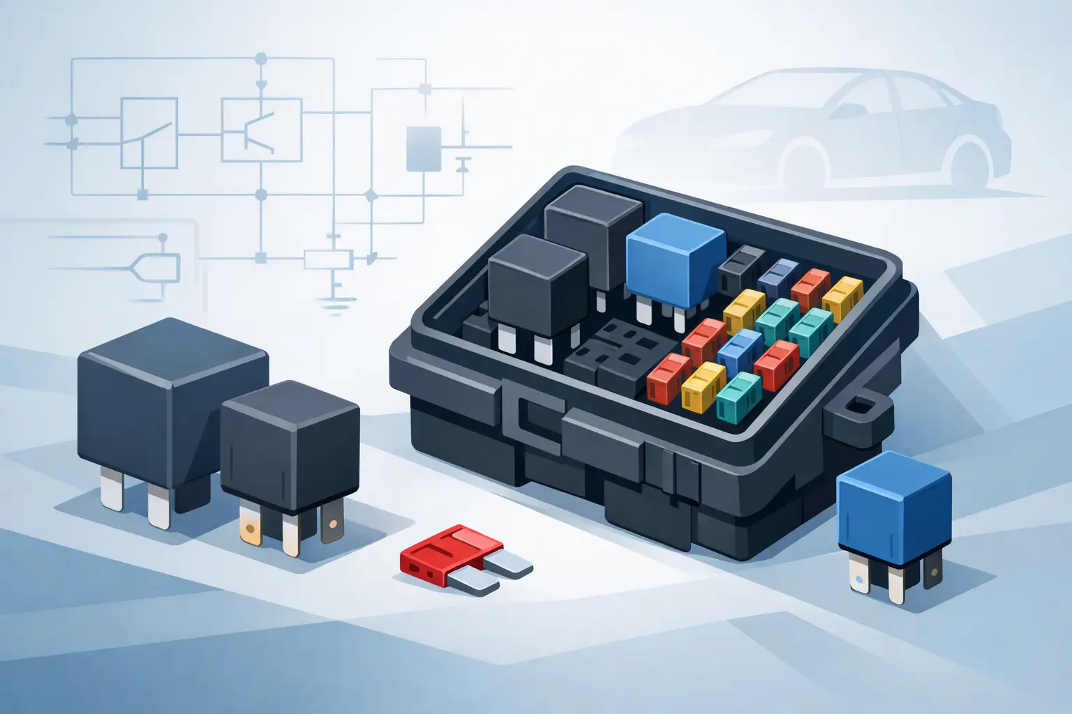
Most fuse box diagrams use a mix of plain text and simple symbols. Fuses are usually shown as numbered cavities with an amp rating. Relays may be named by function or shown as relay blocks with terminal references. Spare fuse positions, empty cavities, and optional equipment slots are often included, which matters because an empty space is not always a missing part.
You will also see labels tied to system names rather than component names. That can slow down newer DIY users. For example, a fuel pump circuit may be protected under ECM, PCM, or INJ depending on how the manufacturer groups the load. The relay you need may not say Fuel Pump Relay on the cover, even if that is the function you are testing.
Why the wrong diagram causes bad diagnosis
A mismatched fuse box diagram does more than waste a few minutes. It can push the diagnosis in the wrong direction.
Say the radiator fan will not come on. You check a chart from a similar model, pull the listed fan fuse, and it tests good. You then move on to the fan motor, temperature sensor, or control module. Later you find out the actual vehicle uses a different underhood box and the fan fuse was in another position entirely. Nothing was wrong with the motor. The reference was wrong.
The same thing happens with relay-swapped testing. On some vehicles, several relays share the same case size and footprint, so swapping a known-good relay can be a fast check. On others, the relay may look similar but serve a different logic or current path. If the diagram does not match the exact vehicle, that shortcut becomes unreliable.
This is where vehicle-specific information pays for itself. At https://Carwiringnew.com, users can narrow diagrams by year, make, model, and component, which is the practical way to avoid broad manual data when the job is specific.
Using relay and fuse box diagrams during real troubleshooting
The best use of a fuse box diagram is as part of a sequence, not as a standalone answer. Start with the symptom. Then identify the affected system and the related fuse or relay. After that, verify power, ground, and control where the diagram points you.
For a dead power window, for example, the diagram helps you confirm whether the issue is tied to a dedicated window fuse, a retained accessory power relay, a door module feed, or a driver master switch circuit. On some vehicles, one blown fuse disables all windows. On others, the main fuse is fine and the actual fault is downstream in a breaker, module, or switch network.
For a crank-no-start, the relay box diagram helps narrow the first checks. You can identify the starter relay, ignition feed, PCM power relay, fuel pump relay, and injector or ECM fuse locations. That does not mean the fuse box is always the problem. It means you stop guessing where the first electrical checks belong.
When a fuse tests good but the circuit still fails
This is a common trap. A fuse can look good and still not tell the whole story. You may have power on only one side, poor terminal tension in the box, corrosion under the panel, or a relay that clicks but does not pass load current. The diagram gives location and assignment, but testing still matters.
That is why continuity alone is not enough on loaded circuits. Voltage drop, feed verification, and control-side checks matter, especially on late-model vehicles where modules wake and sleep based on network commands. A relay and fuse box diagram gets you to the right point in the system. It does not replace the meter.
What to look for in the right diagram source
Speed matters, but accuracy matters more. If you are choosing a diagram source, make sure it lets you search by exact vehicle details and component, not just by make or platform family. Fuse boxes change too often for broad matches to be dependable.
You also want clear labeling. The useful diagram is the one that distinguishes underhood from interior panels, identifies relay positions, and maps circuits in a way that supports testing. A blurry scan of a cover label may be enough for a simple fuse pull, but it is not enough when multiple systems share feeds or when optional equipment changes panel assignments.
Finally, think about the job you are doing. If you are adding accessories, a fuse box layout alone may not be enough. You may also need wiring diagrams for ignition-switched power, lighting circuits, trailer wiring, or body control module inputs. It depends on whether you are replacing a failed part, tracing an intermittent fault, or installing something new.
Guide to relay and fuse box diagrams for faster repairs
The fastest electrical repair usually starts with the right reference, not the first tool you grab. A good guide to relay and fuse box diagrams helps you identify the correct panel, the correct cavity, and the correct circuit before you pull parts or replace anything.
That matters whether you are a DIY owner fixing one issue in the driveway or a shop trying to keep a bay moving. Electrical work gets expensive when diagnosis starts with assumptions. The right diagram cuts that down.
If the fuse panel layout in front of you does not match what you found online, stop there. Recheck year, engine, trim, and box location before you go further. Five extra minutes spent confirming the correct diagram is usually cheaper than one wrong hour of testing.