Alternator Wiring Diagram Troubleshooting
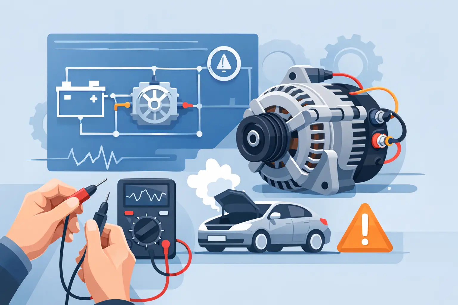
A charging problem usually stops being mysterious the second you stop guessing and start reading the circuit. That is the real value of alternator wiring diagram troubleshooting. If the battery light is on, the battery keeps going dead, or the alternator tests good on the bench but not in the vehicle, the diagram tells you what the alternator needs to work and what is missing.
Most alternator faults are not alternator faults. They are power feed problems, blown fuse links, bad grounds, damaged connector pins, failed sense circuits, or missing ignition feed on the exciter wire. Replacing parts before checking the wiring wastes time and usually creates a second problem – now you are diagnosing both the original fault and a new installation variable.
What the diagram should tell you first
Before you touch the meter, look at the exact diagram for the exact vehicle. Alternator circuits vary more than many people expect. A basic older setup may have a BAT output stud and a simple regulator connection. A newer system may use a PCM-controlled alternator with LIN, GENCOM, or duty-cycle control lines, plus a separate sense wire and charge indicator circuit.
That difference matters because the test path changes with the design. On one vehicle, no charge may mean a failed fuse link between the alternator output and battery. On another, it may mean the engine control module is not commanding output. If you use a generic charging-system test on the wrong system, you can get good numbers at the wrong point and miss the fault entirely.
At minimum, the wiring diagram should identify the alternator output circuit, battery supply path, ground path, regulator or field control wires, ignition or exciter feed, charge warning lamp circuit if equipped, and any related fuses, fusible links, mega fuses, splice points, and modules.
Alternator wiring diagram troubleshooting starts with circuit type
The fastest way to narrow the fault is to identify which charging system you are working on. Most setups fall into a few practical categories.
A one-wire alternator is simple but not common in stock late-model vehicles. It self-excites and usually relies on engine RPM to begin charging. If it does not charge at idle after startup, that may be normal for the design, or it may point to an internal problem.
A three-wire setup usually includes the main battery output, a sense wire, and an ignition or lamp/exciter wire. These systems are straightforward to diagnose because each wire serves a clear function. If the exciter wire never gets switched voltage, the alternator often will not turn on.
Computer-controlled systems are less forgiving. The alternator may have a heavy output cable but rely on a control module for command and monitoring. Here, a missing control signal, module fault, or communication issue can look exactly like a bad alternator. The diagram is what separates those possibilities.
A practical test order that saves time
Start at the battery and work outward. With the engine off, verify battery state of charge first. A weak battery can distort charging tests and lead you in circles. Then inspect the belt drive. A slipping belt can produce low output without any wiring fault at all.
Next, check voltage at the alternator B+ output stud. If you have battery voltage there with the engine off, the main charge cable likely has continuity to the battery, at least at rest. If you have no voltage there, stop and trace the output path on the diagram. Look for a blown mega fuse, open fusible link, or disconnected cable.
Then check the plug at the alternator. This is where alternator wiring diagram troubleshooting usually pays off quickly. One terminal may need ignition voltage with key on. Another may be a sense line that should read near battery voltage. Another may be a control wire from the PCM that needs scope or scan-tool interpretation, depending on the system.
Do not treat every small wire as interchangeable just because the connector fits. Terminal function matters more than wire count. The diagram tells you what each cavity does, wire colors, splice locations, and where that circuit goes next.
Common faults the diagram helps expose
An open output circuit is one of the most common no-charge conditions. The alternator may produce voltage internally, but if the output cable is open between the alternator and battery, the battery never sees it. On the diagram, trace from the alternator B+ terminal through every protection device and splice to the battery positive terminal.
A missing exciter or ignition feed is another common issue. Many alternators need switched voltage to start charging. If the charge warning lamp circuit or ignition feed circuit is open, the alternator may sit there doing nothing. This is why a vehicle can have a new alternator and still show battery voltage only.
Bad grounds are easy to overlook because the alternator case may appear grounded through the bracket. Sometimes it is. Sometimes corrosion, paint, hardware changes, or broken engine-to-chassis grounds add enough resistance to reduce charging under load. The diagram helps you locate dedicated ground points and shared engine grounds that affect the circuit.
Sense wire problems can cause overcharging or undercharging. If the regulator reads low voltage on the sense circuit because of an open, corrosion, or high resistance, it may drive output too high. If the sense circuit is shorted or reading incorrectly, charging strategy changes. This is one of those faults where voltage numbers alone can mislead you unless you know what the regulator is supposed to monitor.
PCM or regulator command issues depend heavily on vehicle design. On newer systems, the alternator is sometimes just one part of a larger charging strategy. Battery current sensors, engine load, temperature inputs, and control module logic all affect operation. If the wiring diagram shows a control module in the middle of the circuit, treat the charging system like a networked system, not just a generator with a plug.
How to read voltage drop instead of just voltage
A circuit can show 12 volts and still fail under load. That is why voltage drop testing matters. On the positive side, measure from the alternator output stud to the battery positive terminal with the engine running and loads on. Excessive drop points to resistance in the cable, fuse, link, or connection.
On the ground side, measure from the alternator case to the battery negative terminal. If voltage drop is high there, the ground path is weak. The exact acceptable number depends on the circuit and load, but the point is simple: low resistance paths keep charging current moving. The diagram tells you every connection in that path so you know where to split the circuit and isolate the bad section.
This is where exact vehicle information matters. Shared grounds can carry multiple systems. A bad ground near the engine block may affect charging, sensors, and lighting at the same time. If you are only checking the alternator connector and not the full path shown on the diagram, you can miss the real fault.
Alternator wiring diagram troubleshooting on modified vehicles
Aftermarket audio, remote starters, winches, lighting, and engine swaps change the rules. Added loads can expose weak factory cables or poor grounds. Poorly installed accessories can also damage charging circuits, especially if someone tapped into ignition feed, battery sense, or charge lamp wiring.
If the vehicle has been modified, compare what is in front of you to what the diagram says should be there. If wire colors do not match, connectors are repinned, or fuse protection has been bypassed, do not assume the factory test path still applies. Diagnose the actual circuit, but use the factory diagram as the baseline.
That is also where vehicle-specific diagrams save time. A generic charging diagram will not show the exact splice pack, fuse cavity, or connector view you need. If you need the correct alternator circuit by year, make, model, and component, Carwiringnew.com is built for that exact lookup process.
When the alternator tests good but the vehicle still does not charge
This usually means the alternator is missing one of its requirements in the vehicle. It may have no battery feed, no exciter feed, no ground, no sense input, or no control command. Bench tests can confirm the unit can charge under test conditions. They do not prove the vehicle is delivering the right inputs.
It can also mean the opposite problem – the alternator is charging, but the battery is not accepting or holding the charge. A battery with an internal fault, high-resistance terminals, or severe parasitic drain can make the charging system look weak. The diagram will not diagnose battery condition for you, but it will keep you from blaming the wiring when the fault is elsewhere.
The best approach is simple. Identify the circuit type, verify power and ground, verify the turn-on or control path, and trace every protection device shown on the diagram. When a reading does not make sense, go back one point on the circuit and test again. The fault is usually between the last good point and the first bad one.
Good electrical diagnosis is not about memorizing alternator theory. It is about following the exact path the current is supposed to take. Get the right diagram first, and the rest of the job gets a lot shorter.