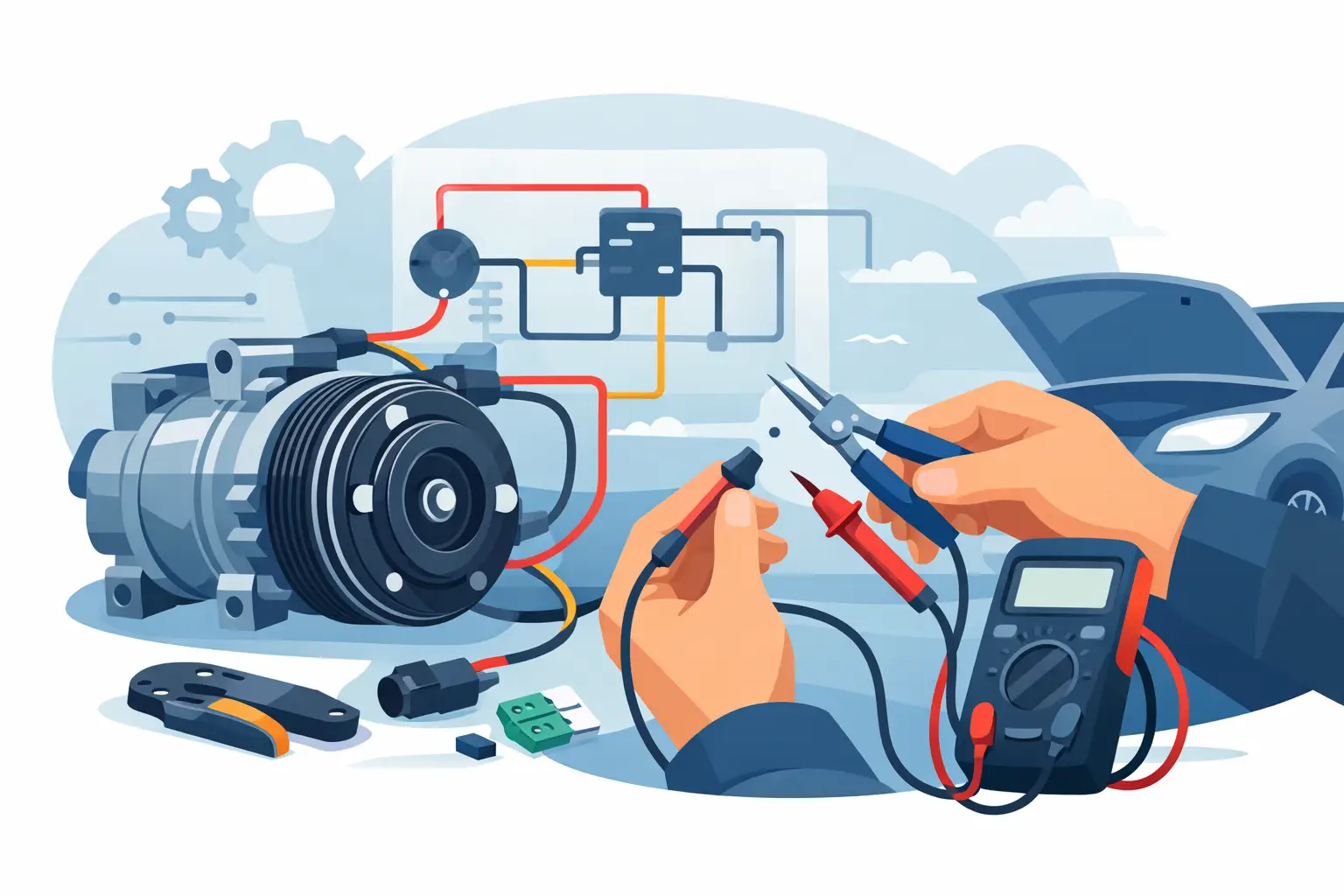
A/C Compressor Clutch Wiring Diagram Repair
When the A/C clutch will not engage, guessing gets expensive fast. An A/C compressor clutch wiring diagram repair starts with the right circuit for the exact vehicle, because wire colors, relay control, pressure switch logic, and PCM involvement vary more than most people expect.
What the circuit usually includes
On a basic system, the clutch circuit looks simple. Battery power feeds a fuse, then a relay, then the compressor clutch coil, with ground completing the path. In the real world, that path often runs through pressure switches, an evaporator temperature input, the HVAC control head, and sometimes the PCM or BCM before the relay is allowed to close.
That matters because a dead clutch is not always a bad clutch. The control side may be blocking engagement on purpose due to low refrigerant pressure, an engine protection strategy, or a fault seen by the module. If you skip the diagram and jump straight to the compressor connector, you can waste time replacing a part that never lost its command in the first place.
A/C compressor clutch wiring diagram repair starts with vehicle fitment
There is no universal clutch diagram that works across years, trims, and engine options. Even within the same model line, one version may use a simple two-wire clutch feed while another routes the request signal through the PCM and controls the relay on the ground side.
That is why the first step is not testing. It is pulling the exact wiring diagram by year, make, model, engine, and component. If you are working from a generic manual or a forum screenshot, stop there. Get the correct clutch circuit before you start checking voltage.
How to approach the fault logically
A no-engagement complaint usually falls into one of four buckets. The clutch is not being commanded on. The clutch is being commanded on but power never reaches it. Power reaches it but the ground path is bad. Or the clutch coil itself has failed mechanically or electrically.
The quickest way through those possibilities is to follow the circuit in order, not jump around the engine bay hoping to catch the problem by luck.
Step 1: Confirm the symptom
Set the A/C to max, blower on, and command cooling with the engine running. Watch the clutch hub, not just the pulley. The pulley can spin all day with the belt while the clutch never pulls in.
If the clutch cycles briefly and drops out, that is a different problem than no engagement at all. Short cycling can point toward pressure conditions, sensor input, or control logic. No movement at all often points toward missing power, missing ground, an open coil, or a blocked command.
Step 2: Check the fuse and relay using the diagram
Do not assume the fuse label tells the whole story. Many vehicles use separate fuses for the load side and the control side of the relay. One powers the clutch. Another powers the HVAC request or module feed.
Use the diagram to identify the exact fuse cavities and relay terminals. Then verify battery voltage where it should exist. If the relay has terminal numbers, you usually want to know three things: is there constant battery power at the feed, is the control side receiving a command, and does output power leave the relay when it is energized.
A relay can click and still fail under load. A fuse can look good and still have no feed to it. Test both sides with a meter or a test light.
Step 3: Verify clutch connector power and ground
At the compressor connector, check for voltage with the A/C commanded on. If you have battery voltage on the feed side and a known good ground, the clutch should engage unless the coil is open or the air gap is excessive.
If you have no voltage there, move backward through the circuit. If you have voltage but the clutch does not engage, unplug the connector and check coil resistance against the service spec if available. An open circuit reading usually means the clutch coil is done.
Ground-side failures are easy to miss. Some systems ground the clutch directly to the engine. Others use a controlled ground path. Voltage alone does not prove the circuit can carry current. A voltage drop test under command is often more useful than a simple continuity check.
Where repairs commonly go wrong
The most common mistake is bypassing the clutch to “see if it works” without understanding the control strategy. Yes, jumping power directly to the clutch can confirm whether the coil pulls in, but it tells you nothing about why the vehicle is withholding command. On some systems, forcing engagement with low refrigerant or a blocked condenser fan issue can create a bigger problem.
The second mistake is trusting wire color more than circuit position. Wire colors change between production dates and engine packages. Terminal location and connector ID from the diagram matter more.
The third mistake is ignoring pressure and sensor inputs. If the low-pressure switch is open because the system charge is low, the clutch may be doing exactly what it should. That is not a wiring repair. It is a system condition that needs to be addressed before electrical parts get blamed.
A/C compressor clutch wiring diagram repair for module-controlled systems
On newer vehicles, the HVAC panel may only send an A/C request. The PCM or BCM then decides whether to ground or power the relay based on refrigerant pressure, coolant temperature, engine load, and fault status. In that setup, the clutch circuit has a command layer and a load layer.
The load layer is the high-current path from fuse to relay to clutch. The command layer is the low-current logic path that tells the relay to switch. A repair stalls out when those two layers get mixed together.
If the relay load side is healthy but the control side never gets triggered, look at the request signal, pressure transducer reference and signal wires, and any module outputs shown in the diagram. That is where the exact vehicle-specific schematic saves time. You can see whether the module is supposed to supply power, provide ground, or wait for another input before it allows clutch engagement.
Practical test results and what they usually mean
If there is no power at the clutch and no power leaving the relay, suspect the relay, its feed, or the command side preventing activation. If there is power leaving the relay but none at the clutch connector, suspect an open wire, connector damage, or corrosion in the harness between those points.
If there is full voltage at the clutch connector and a clean ground, but no engagement, the clutch coil or the clutch air gap is likely the issue. If there is low voltage at the connector under load, you may have high resistance upstream, often from heat-damaged terminals or a failing relay contact.
If the relay never receives a command, do not force the circuit yet. Check refrigerant pressure inputs and module logic first. Electrical diagnosis and A/C system diagnosis overlap here, and the answer depends on which part of the circuit is being blocked.
Repair decisions that save time
When the fault is in the harness, repair the wire with the same gauge and a sealed connection, especially near the compressor where heat, oil, and vibration are constant. If the connector is burnt or loose, replace the connector body and terminals, not just the wire pigtail if the terminal fit is already poor.
When the clutch coil tests open, the repair path depends on the compressor design. Some vehicles allow clutch service separately. Others make compressor replacement the smarter move once labor and access are considered. The cheapest part is not always the cheapest repair.
For repeat electrical work, having the exact diagram on hand matters more than having every tool in the box. The right circuit cuts out the usual backtracking through wrong fuses, wrong relays, and wrong connector views. That is the point of using a vehicle-specific source such as Carwiringnew.com when the job is component-level diagnosis, not general browsing.
Before you call it fixed
After the repair, command the A/C on and verify clutch engagement, vent temperature change, and normal cycling. Then recheck the repaired section for heat, voltage drop, and connector fit. A clutch that engages for 30 seconds and quits still has a problem, even if the original open wire is gone.
Good wiring repair is less about getting the clutch to click once and more about proving the whole circuit works the way the vehicle was designed to control it. When the diagram matches the exact vehicle, that proof gets a lot easier.
If the clutch circuit has you chasing your tail, slow down and identify whether you are dealing with a missing command, a missing power path, or a failed clutch. The right diagram turns that from a parts-swapping job into a clean diagnosis.