Trailer Wiring Diagrams That Actually Match
You can wire a trailer perfectly and still end up with dead running lights or a turn signal that flashes like it has a mind of its own. Most of the time, the problem is not the trailer. It is that the vehicle side was guessed at – wrong connector, wrong circuit location, or the wrong assumption about what “standard colors” means on that particular year/make/model.
A trailer wiring diagram for vehicle-specific fitment is the difference between finishing the job in one pass and spending your afternoon chasing blown fuses, bad grounds, and phantom voltage.
What a trailer wiring diagram is actually telling you
A diagram is not just “green goes to right turn and yellow goes to left.” A usable diagram tells you where the vehicle provides those signals, what module or fuse protects them, and whether the vehicle even outputs a traditional 12V lighting feed.
That last part matters. Many late-model vehicles do not want you tapping directly into rear lamp wires because the lighting is controlled by a body module. On those vehicles, a basic splice can create bulb-out warnings, hyperflash, or intermittent shutoffs. A diagram helps you confirm whether you are dealing with a straightforward signal wire or a computer-controlled circuit that needs an interface.
Know your connector before you chase wires
Most confusion starts with the connector style. In the US you will commonly see a 4-way flat, 5-way flat, 6-way round, or 7-way RV blade. The connector determines how many functions you can support and which functions are even present.
A 4-way flat is typically the minimum set: ground, tail/running lights, left turn/brake, and right turn/brake. A 7-way adds circuits like electric trailer brakes, 12V auxiliary power, and reverse/backup.
If your trailer has electric brakes and you are trying to run it from a 4-way, there is nothing “wrong” with your wiring – you simply do not have the circuits available.
The “standard color code” is only standard for the trailer side
On trailers, color conventions are common enough that many people treat them as law. On vehicles, wire colors vary widely by manufacturer and model year. Even the trailer side can be inconsistent if someone repaired it before you.
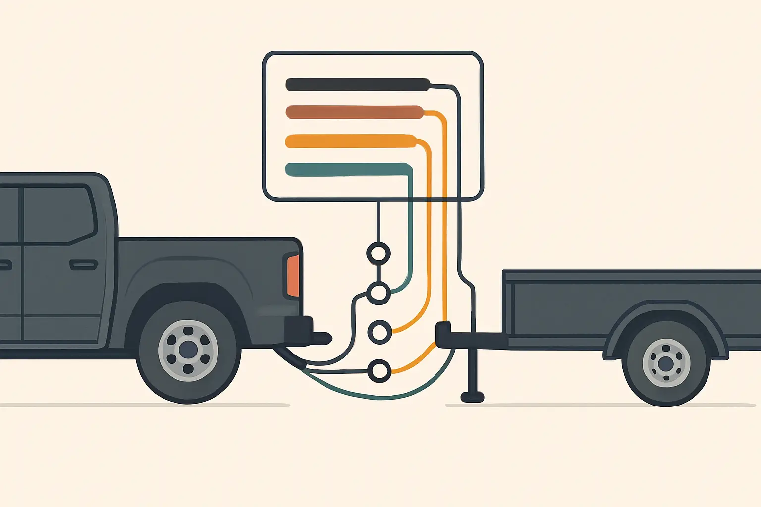
For trailer connectors, you will often see these conventions:
- White: ground
- Brown: tail/running lights
- Yellow: left turn/brake
- Green: right turn/brake
- Blue (7-way): electric brake output
- Black or red (7-way): 12V auxiliary power
- Purple (7-way): reverse
Treat this as a starting point, not proof. The diagram and a quick test are what confirm reality.
2-wire vs 3-wire tail light systems (this changes your plan)
The vehicle’s rear lighting design affects how you tie in.
On many vehicles, the brake and turn share a single filament/circuit per side. That is the classic 2-wire setup: one wire for tail/running, and one wire that does both brake and turn for that side.
Other vehicles separate brake and turn into different circuits (common on some imports and certain trim packages). That is closer to a 3-wire arrangement at the lamp level.
Why you care: most small trailers expect combined brake/turn on each side. If your vehicle outputs separate brake and turn signals, you will need a converter module so the trailer gets the combined signal it expects. A vehicle-specific trailer wiring diagram is how you confirm which system you have before you start splicing.
Where installers waste time: guessing the pickup point
The “easy” approach is to pull a tail light and probe wires until something looks right. That can work, but it is also where mistakes happen:
- You may find a wire that looks like a turn signal but it is a low-current signal to a control module.
- You may pick up a circuit before it is fused the way you expect.
- You may miss a factory trailer tow connector that is already pinned and waiting.
Many trucks and SUVs have a factory tow prep harness or an unused connector behind a trim panel, under the rear bumper, or near the spare tire. If your vehicle has it, the cleanest job is using that connector rather than cutting into lamp wiring.
A diagram shows whether that connector exists and what each pin does.
A practical workflow that avoids rework
If you want the job to go fast, do it in this order.
Step 1: Confirm what the trailer needs
Check the trailer plug type and whether it has electric brakes, reverse lights, or a battery/auxiliary circuit. This decides whether you need a 4-way, 5-way, or 7-way connection.
Step 2: Identify the vehicle’s intended trailer wiring path
Look for an existing tow connector, a junction block, or a dedicated trailer module. If the vehicle is known for computer-controlled lighting, assume you will need an approved interface unless your diagram shows a true trailer output.
If you want a fast way to pull the right diagram by exact fitment, use the Vehicle Selector at https://Carwiringnew.com to get a wiring diagram mapped to your year, make, model, and the specific component or circuit you are working on.
Step 3: Verify signals with a test light or multimeter
Do not trust wire color alone. Back-probe and verify:
- Tail/running lights: steady 12V with parking lights on
- Left and right turn: pulsing 12V when each turn signal is on
- Brake: steady 12V when pedal is pressed
- Reverse: 12V in reverse (key on, brake applied as needed)
If the vehicle uses PWM (pulse-width modulation) or a low-current signal, a basic incandescent test light can load the circuit and cause odd behavior. In those cases, use a digital multimeter and follow the diagram to the correct output point.
Step 4: Ground first, then chase everything else
Bad grounds create “impossible” symptoms: both turn signals glow dimly, brakes feed into running lights, or the trailer lights work only when the coupler is at a certain angle.
On the trailer side, ground should be bolted to clean metal on the frame. On the vehicle side, the ground should be tied to a known-good chassis ground point or the dedicated ground wire in the tow harness.
If you are using a 4-way flat, the white ground wire is not optional.
Step 5: Protect the circuits
If you are adding a powered converter or running a 12V auxiliary feed for a 7-way, that power line needs proper circuit protection near the battery. Some vehicles have a factory fuse location you must populate to activate the tow circuit. Others require an add-on breaker or inline fuse.
This is where diagrams save you from guessing. The correct fuse location, relay position, and wire gauge depends on the vehicle and the load.
4-way flat wiring: what you should see at the plug
When the vehicle and trailer both use a basic 4-way flat, troubleshooting can be fast if you know what “good” looks like.
At the vehicle-side connector:
- Ground should have continuity to chassis
- Tail/running should show 12V with parking lights on
- Left turn/brake should pulse with left turn, and go steady with brakes
- Right turn/brake should pulse with right turn, and go steady with brakes
If the vehicle signals check out but the trailer does not light, you are usually dealing with a trailer ground, a bad bulb, corrosion in the plug, or a broken wire inside the trailer frame.
7-way RV blade: the common trouble spots
A 7-way adds capability, but it also adds places to miswire.
The two circuits that cause the most headaches are the electric brake output (blue) and the 12V auxiliary feed (black/red). People swap these, then wonder why the trailer brakes lock up when they turn on headlights, or why the breakaway battery never charges.
Another common issue is assuming the center pin is always reverse. Pin location can vary by connector style and how it is labeled. Always use the diagram and confirm with a meter.
Also, electric trailer brakes are not powered directly from a random 12V source. They are controlled by a brake controller, and the brake output wire should run from that controller to the 7-way brake pin. If you do not have a controller installed, you can wire the 7-way perfectly and still have no trailer braking.
When a “simple splice” is the wrong move
It depends on the vehicle.
If your vehicle has traditional incandescent lamp circuits and you are tapping into a true 12V output, a quality splice, heat-shrink, and proper routing can last for years.
If your vehicle has LED tail lamps, bulb monitoring, or body control module outputs, splicing can introduce problems that look like wiring faults but are really control-module protection behavior. That is when a powered interface or vehicle-approved tow module becomes the correct fix, even if it costs more up front.
The trade-off is straightforward: the cheapest method can be the slowest if it triggers electrical quirks you then have to diagnose.
Quick diagnostics when something does not work
If one function is dead, isolate it.
If running lights are out but turns work, suspect the brown wire circuit, trailer-side corrosion, or a blown park-lamp fuse on the vehicle. If only one side turn/brake is out, suspect the yellow or green circuit, a bad ground on that side of the trailer, or a pin that is pushed back in the connector.
If everything is dim or backfeeding, stop and fix the ground before replacing parts. If the vehicle-side output is missing, follow the diagram upstream to the fuse, relay, module output, or tow connector. That is faster than poking random wires.
A clean trailer wiring job is not about creativity. It is about matching the vehicle’s actual circuits to the trailer’s needs, verifying with a meter, and making connections you will not have to revisit the next time it rains.