Trailer Brake Controller Wiring Diagram Vehicle Specific
If your brake controller install starts with a universal diagram, you’re already risking wasted time. A trailer brake controller wiring diagram vehicle specific gives you the exact wire colors, connector locations, fuse protection, and circuit routing for the vehicle in front of you – not a close match, not a forum guess, and not a generic tow package layout.
That matters because brake controller wiring is simple only until it isn’t. One truck may have a factory tow package with a blunt-cut brake output wire under the dash. Another may need a dedicated power feed run through the firewall. A third may have the connector taped to the main harness behind the kick panel, while a similar trim level on the same model line does not. If you are trying to install or troubleshoot by assumption, this is where jobs stall.
Why a vehicle-specific brake controller diagram matters
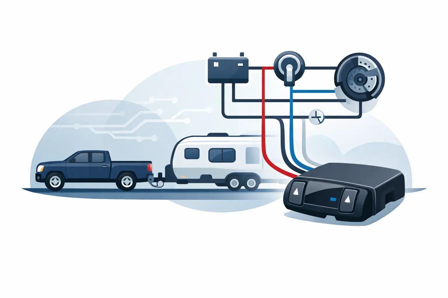
A brake controller needs the same core circuits on almost every vehicle: battery power, ground, brake switch input, controller output to the trailer connector, and often illumination or data-related inputs depending on the setup. The problem is that those circuits are not always found in the same place, and they are not always identified the same way.
A generic diagram shows theory. A vehicle-specific diagram shows execution. That is the difference between knowing what a controller needs and knowing exactly where to connect it on a 2014 Ram 1500 versus a 2019 Ford F-250 or a 2008 Silverado without the factory tow option.
This is also where many miswires happen. Installers may tap the wrong side of the brake switch, grab a wire that is hot in accessory instead of battery, or assume a 7-way brake feed is already active when the vehicle still needs an underhood fuse, relay, or programming step. A correct diagram reduces those mistakes before the first panel comes off.
What a trailer brake controller wiring diagram vehicle specific should show
For this type of job, the right diagram needs more than a basic line drawing. It should identify the power source path, fuse or circuit breaker rating, brake pedal switch circuit, chassis ground point, trailer brake output circuit, and connector locations. On many vehicles, it should also show splice points, junction blocks, and whether a factory tow package changes the routing.
Connector face views are especially useful. Wire color alone is not enough when colors fade, harnesses have been repaired before, or more than one similar connector is under the dash. Pin identification and connector cavity numbering help confirm that you are on the correct circuit before making a connection.
For troubleshooting, the diagram should also let you follow the circuit end to end. If the controller powers up but the trailer brakes do not respond, you need to know whether the fault is at the controller output, a body harness connector, an underbody junction, or the 7-way socket. A vehicle-specific layout saves time because it narrows the fault path fast.
Factory tow package vs non-tow package changes everything
This is where installs split into two very different jobs. A vehicle with a factory tow package often has a dedicated brake controller connector, pre-run brake output wiring, and trailer feed circuits already routed to the rear. In that case, installation may be close to plug-and-play, but only if the diagram confirms the connector location and circuit status.
A non-tow-package vehicle usually requires more work. You may need to run a battery feed with proper protection, route a brake output wire to the rear connector, and confirm whether the existing 7-way or 4-way setup can support trailer brakes at all. Some owners assume a hitch means the wiring is complete. It often is not.
Even within the same model year, trim and equipment level can change the answer. That is why year, make, model, engine, and towing package details matter. The right diagram is matched to the exact vehicle, not the badge on the grille.
Common installation problems caused by the wrong diagram
The most common issue is a bad brake signal source. If the controller is tied into the wrong brake switch wire, it may see constant voltage, no voltage, or the wrong signal profile. That can cause delayed braking, controller errors, or no trailer brake activation.
Power feed mistakes are close behind. Some controllers need a dedicated battery source with a specified fuse or breaker. Pulling power from an accessory circuit or an undersized source may let the controller turn on but fail under load. The problem looks like a controller issue when it is really a supply issue.
Ground faults create another layer of confusion. A weak or shared ground can produce intermittent operation that only shows up with a trailer connected. Without the right wiring diagram, it is easy to chase the trailer side first and miss the vehicle ground point entirely.
Then there is rear circuit confusion. The blue brake output wire at the controller does not help much if you do not know where that circuit travels through the body harness and how it reaches the 7-way connector. This is where vehicle-specific routing earns its value quickly.
How to use the right diagram before you start cutting or tapping
Start by confirming whether the vehicle already has a brake controller provision. Look for a factory connector under the dash, check underhood fuse positions related to towing, and verify what kind of trailer socket is installed at the rear. The diagram should tell you if those pieces are part of the original design or were added later.
Next, trace the required circuits on paper before touching the harness. Identify your battery feed, ground, brake input, and brake output path. If the vehicle uses a plug-in pigtail, confirm the connector view and pin assignments. If it requires hardwiring, confirm the exact tap points and any required protection.
After that, test the circuits. A diagram is the roadmap, but a meter or test light confirms the vehicle has not been altered. This matters on used trucks and SUVs, where aftermarket alarms, remote starts, prior trailer wiring repairs, or body work may have changed what should be there.
When diagnosis is the real job, not installation
A lot of people search for a brake controller diagram because the system worked before and suddenly stopped. In those cases, the controller may not be the failure. A blown tow fuse, damaged rear harness, corroded 7-way socket, broken ground, or open brake output circuit can all produce the same complaint.
A vehicle-specific diagram helps separate controller faults from vehicle wiring faults. If battery power and brake input are present at the controller but there is no output at the rear connector, you can isolate where the circuit is lost. If there is no power at the controller at all, the diagram points you back to the correct fuse, relay, or power distribution point.
That is the practical difference between a real diagnostic workflow and replacing parts based on guesswork.
Getting the correct trailer brake controller wiring diagram vehicle specific
The fastest path is to select the exact vehicle and component instead of searching broad terms and hoping for a match. On https://Carwiringnew.com, the workflow is built around year, make, model, and component selection so you can pull the diagram that fits the vehicle you are actually servicing.
That matters on brake controller jobs because small differences are not small once you are under the dash. Connector location changes, tow-package variations, and circuit routing updates can turn a one-hour install into an all-day correction if you start with the wrong information.
For DIY owners, the benefit is fewer mistakes and less rework. For independent shops and mobile installers, it is speed. The right diagram lets you verify the circuit path, make the connection once, and move on to testing instead of spending billable time comparing conflicting sources.
What to check after the install
Once wired, verify controller power, brake pedal input, manual override function, and brake output at the trailer socket. Then connect the trailer and confirm the controller detects it properly. If the controller powers up but trailer braking is weak, do not assume the vehicle side is finished – check gain settings, trailer ground integrity, brake magnet condition, and connector corrosion.
The key point is simple: a working screen on the controller does not prove the whole circuit is correct. The diagram gets you to the right wiring. Testing confirms the job is done.
If you are about to install or diagnose a trailer brake controller, start with the exact diagram for the exact vehicle. It is the shortest route to a clean repair and the easiest way to avoid doing the same job twice.