Starter Wiring Diagram: Read It, Test It, Fix It
You turn the key and get nothing. No crank, no click, and the dash lights might even look normal. This is exactly where a starter wiring diagram earns its keep – not as a “nice to have,” but as the fastest way to stop guessing and start proving what’s missing: power, ground, or the control signal.
A starter circuit is simple compared to most modern systems, but it’s also full of small decision points (neutral safety, clutch switch, relays, security inputs) that can break the chain. The right diagram, for the exact year/make/model, keeps you from testing the wrong wire at the wrong connector.
What a starter wiring diagram actually shows
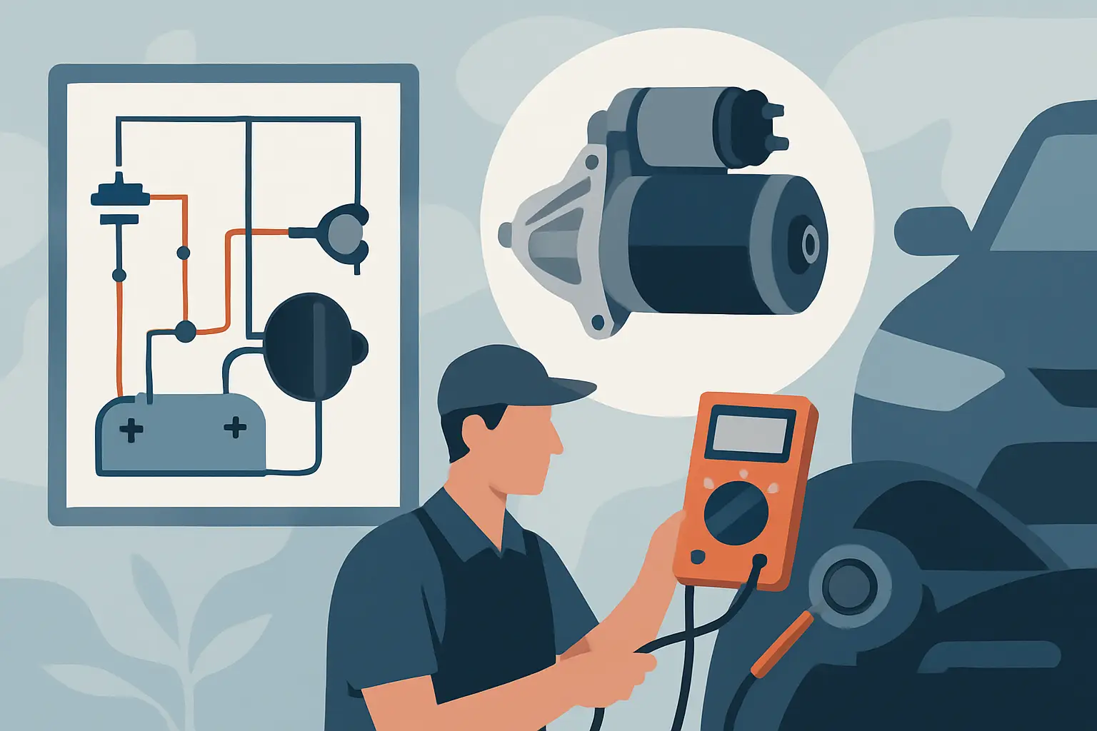
A starter wiring diagram is a map of the starter circuit: how battery power gets to the starter motor, how the solenoid is commanded to engage, and what safety or control devices sit in between. It also shows wire colors, connector locations, splice points, fuse or fusible link protection, grounds, and in many cases the exact terminals on the starter and relay.
Generic “starter circuit” drawings are fine for learning. They are risky for diagnosing. Real vehicles change pinouts, relay locations, and even the direction of current flow depending on options like push-button start, immobilizers, remote start, or transmission type.
The basic starter circuit, in plain terms
Even when the wiring layout differs, most starter systems still boil down to two paths: the high-current path that spins the motor, and the low-current control path that tells the solenoid to connect that high-current path.
High-current side (battery to starter motor)
This is the heavy cable you can see and feel. Battery positive feeds the starter’s main terminal (often labeled B+). When the solenoid closes, that power is sent into the starter motor windings. The return path is through the starter case to the engine block, then back to battery negative through the ground cable.
If this side fails, you may hear a click (solenoid tries to engage) but the motor doesn’t spin, or it spins weakly. Corrosion, loose connections, and voltage drop are common.
Control side (key or button to solenoid “S” terminal)
This side energizes the solenoid coil. Depending on the vehicle, the command may come from the ignition switch, a starter relay, a body control module, a powertrain control module, or some combination.
If this side fails, you usually get no click at all. The starter never receives the signal to engage.
Common components shown on a starter wiring diagram
A good diagram calls out each gate in the chain. The names can vary, but the roles are consistent.
Battery, fusible link, and starter fuse
Many vehicles protect the starter feed with a fusible link or mega-fuse near the battery. A standard fuse panel fuse often protects the control circuit, not the motor feed. The diagram tells you which is which.
Ignition switch or start/stop switch
Traditional key systems feed a “START” output when the key is turned. Push-button systems often send a request signal to a module, which then commands a relay.
Park/neutral safety switch or clutch switch
Automatics typically require Park or Neutral. Manuals typically require the clutch pedal depressed. Some vehicles use a switch directly in series with the start signal. Others send a status input to a module that decides whether to ground or power the relay.
Starter relay
The relay allows a small control current to switch a larger current to the solenoid. On many cars, the relay switches power to the solenoid. On others, a module switches the relay’s ground side. Your diagram will show which side is being controlled.
Starter solenoid and motor
On most starters, you’ll see at least two connections: the large B+ terminal and the smaller S terminal (start signal). Some designs also have an R terminal or additional connections depending on configuration.
Grounds and ground distribution
Grounds are not “implied” when you’re diagnosing. A diagram typically identifies a ground point (G###) and its location. That’s where you verify continuity and voltage drop.
How to read a starter wiring diagram without getting lost
Start by identifying what type of control strategy your vehicle uses, then follow the circuit from the battery to the starter and from the ignition command to the solenoid.
First, locate the starter motor and solenoid on the diagram and note the terminal labels. Then find the starter relay and determine whether the relay is supplying power to the solenoid or supplying ground. That single detail changes how you test the circuit.
Next, look for “in-series” devices that must be closed for cranking: clutch switch, park/neutral switch, any security inhibit, and any module permission. If the diagram shows a module (PCM/BCM) controlling the relay, accept that the “missing piece” might be a logic input (like brake pedal, key authentication, or transmission range signal), not a broken wire.
Using the diagram to diagnose a no-crank step by step
A starter wiring diagram is only useful if you pair it with a meter and a plan. The goal is to find where voltage stops, or where ground is missing, under the exact condition when the vehicle should crank.
Step 1: Confirm the symptom and load
“Won’t start” can be crank-no-start or no-crank. This article is no-crank. If the starter spins but the engine doesn’t fire, you’re in fuel/ignition territory, not starter wiring.
Also note whether there is a click. A click often means the control side is at least partially working.
Step 2: Check battery state and the main connections
A diagram can’t fix a loose terminal. Verify battery voltage, then check the battery posts, battery-to-chassis ground, and engine ground strap. High resistance here can mimic a bad starter.
If you have 12.6 V static but the voltage collapses when attempting to crank, you may be dealing with a weak battery, poor connection, or seized starter. Testing under load is the point.
Step 3: Identify the starter solenoid “S” wire and test for command
Use the diagram to locate the S terminal circuit and its wire color. Backprobe the connector or terminal safely.
Have a helper turn the key to START (or press the start button) while you watch the meter. If you get proper voltage on the S wire during the crank request and the starter doesn’t engage, the fault is likely at the starter, the solenoid, or the high-current feed/ground.
If you get no voltage at S during a crank request, you move upstream to the relay, switches, or module logic.
Step 4: Prove relay input and output
The diagram will show relay terminal numbers (common ones are 30, 85, 86, 87) or manufacturer-specific labels.
You’re looking for two things: does the relay have the correct feed (power) on the supply side, and is it being commanded (power or ground) on the coil side? If the coil is commanded and the relay does not click or does not pass power, you have a relay or socket issue.
It depends on the vehicle whether the relay is hot at all times or only in START. The diagram tells you, and it prevents misdiagnosis.
Step 5: Verify safety switch operation with the diagram
If the circuit passes through a park/neutral switch or clutch switch, test it in the position it should allow cranking. Many DIYers test continuity with the connector unplugged and call it good. Better is confirming the switch actually passes voltage (or ground) in the real circuit, because corrosion and pin fit issues show up under load.
Step 6: Don’t skip voltage drop on the high-current path
If the starter clicks but won’t turn, measure voltage drop on the positive cable from battery to starter B+ while attempting to crank. Then measure on the ground side from starter case/engine block to battery negative.
A wiring diagram helps here by identifying the exact ground points and any junctions or distribution studs in the path. A shiny battery terminal doesn’t guarantee the connection at the distribution block is good.
Trade-offs and “it depends” scenarios you’ll see in real vehicles
On older vehicles, the ignition switch may send power directly to the solenoid through a single wire, and diagnosis is straightforward.
On newer vehicles, the start request can be a low-voltage signal that tells a module to energize a relay. That means a no-crank can be caused by a missing permission input (anti-theft, brake switch, range sensor) even when the wiring is intact. The diagram is still essential, but you may also need scan tool data to see why the module refused to crank.
Remote start and aftermarket alarms add another layer. They often splice into the starter control wire or intercept ignition switch outputs. If your diagram says the S wire should be hot in START and it’s not, but the vehicle has add-ons, inspect those splices before condemning factory parts.
Getting the right diagram fast
If you’re using a starter wiring diagram to make a repair decision, make sure it matches the exact vehicle and the exact starter system configuration. That means year, make, model, engine, and sometimes trim or transmission.
If you want vehicle-specific diagrams that you can pull by fitment and component instead of scrolling through generic manuals, you can use the Vehicle Selector on Carwiringnew.com and target the starter circuit directly.
The best use of a starter wiring diagram is simple: use it to pick one wire, one connector, and one test point at a time, then follow the result. When you let the diagram drive the next check, the no-crank problem usually stops being mysterious and starts being measurable – and that’s when you get the car out of the driveway and back on the road.