Blower Motor Resistor Wiring Diagram Basics
A blower fan that only works on high speed usually points to the same place fast – the resistor circuit. But guessing at wire colors, pin locations, or which terminal should have power is how good parts get replaced for no reason. A blower motor resistor wiring diagram gives you the shortest path to the fault.
If you are tracking down an HVAC blower issue, the diagram matters because this circuit is not identical across vehicles. Some systems switch power. Some switch ground. Some use a resistor pack with visible coils. Others use a solid-state control module that gets lumped under the same name even though the test approach is different.
What a blower motor resistor wiring diagram shows
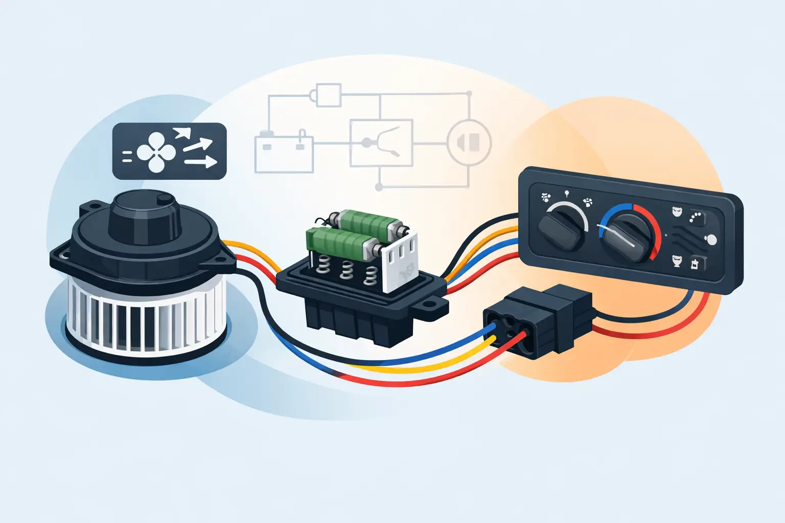
At a basic level, the diagram maps the path from the fuse or relay to the blower switch, resistor, control module, blower motor, and ground. On many older manual HVAC systems, lower fan speeds run current through different resistor values, while high speed bypasses the resistor completely. That is why a failed resistor often leaves you with high speed only.
A proper blower motor resistor wiring diagram also shows connector cavities, splice points, wire colors, fuse protection, and sometimes ground locations. Those details save time. If cavity 3 should have battery voltage with the key on and the fan switch set to medium, that tells you more than a forum post saying, “check the resistor.”
The exact layout depends on the system. In one vehicle, power may leave the blower fuse, pass through a relay, then go to the motor and through the resistor to ground. In another, the switch may feed the resistor first, then the motor. The difference changes where you probe and what readings make sense.
How the circuit usually works
Manual HVAC systems
The most common resistor setup uses several resistor paths to reduce current and slow the blower motor. The fan speed switch selects which path is used. Low speed routes current through the most resistance. Medium speeds route current through less. High speed usually bypasses the resistor through a dedicated relay or direct switch contact.
In practical terms, if low, medium-low, and medium are dead but high works, the resistor pack, connector, or thermal fuse becomes the first place to inspect. If no speeds work, you may be dealing with a fuse, relay, bad motor, failed switch, missing ground, or a melted connector rather than the resistor alone.
Automatic climate control and solid-state modules
Some newer vehicles use an electronic blower motor control processor instead of a simple resistor pack. The symptom can look similar, but the wiring diagram becomes even more important because the module may have a power feed, ground, blower output, ignition feed, and a control signal from the HVAC control head or body module.
Calling all of these parts a resistor is common in parts counters and search results, but diagnosis is not one-size-fits-all. A resistor pack can often be checked for open circuits and heat damage. A solid-state module may require checking reference voltage, command signal, and voltage drop under load.
Reading the diagram without wasting time
Start with the circuit path, not the whole page. Find the blower motor, then trace backward to the power source and forward to ground, or the other way around depending on the style of diagram. Ignore unrelated HVAC controls until you know how blower current is supposed to move.
Pay attention to labels for fuses, relays, splice packs, and grounds. A blower circuit can fail at any of those points. If the diagram shows Fuse 17 feeding the blower relay and then connector C202 cavity B going to the resistor, you now have test points. That is what turns a diagram into a repair tool.
Wire color helps, but do not rely on color alone. Harness repairs, production changes, and faded insulation can mislead you. Connector pin numbers and component locations are more dependable.
What to test first when the blower fails
With the correct blower motor resistor wiring diagram in front of you, the first checks are simple. Confirm power at the fuse. Confirm the motor has a usable ground or power feed, depending on how the circuit is switched. Then check whether the resistor or module is receiving what it needs to operate.
If high speed works and lower speeds do not, test the resistor connector carefully. Heat damage is common. A melted pigtail can create resistance, drop voltage, and burn up the replacement part if the connector is not repaired. This is one of the most missed problems in blower circuits.
If no speeds work, unplug the blower motor and verify whether battery voltage and ground are present when the switch is commanded on. If both are there and the motor does not run, the motor is likely bad. If one side is missing, return to the diagram and move upstream one point at a time. That is faster than replacing the resistor on suspicion.
Common wiring patterns you will see
Four- or five-wire resistor packs
A common manual system uses one wire from the fan switch and multiple output paths through the resistor elements, plus a high-speed bypass. In some vehicles, the resistor assembly also includes a thermal limiter. When that opens, lower speeds can disappear even if the resistor coils look intact.
Relay-assisted high speed
Many systems use a blower relay for high speed because current draw is too high for the switch alone. The diagram will show a separate high-speed path that does not pass through the resistor. This is why the blower can run strong on high with every lower setting dead.
Ground-side speed control
Some manufacturers control fan speed on the ground side instead of the power side. If you assume every blower circuit is power-switched, your voltage readings can look wrong when the circuit is actually working as designed. The diagram settles that immediately.
Where people go wrong
The biggest mistake is using a generic diagram or one from the wrong engine, trim, or HVAC option. Blower circuits can change within the same model year. Manual climate control and automatic temperature control often use different parts and different wiring.
The second mistake is checking voltage with no load and calling the circuit good. A corroded connector can show near battery voltage on a meter but collapse under load. If the diagram points you to the power feed and ground path, use voltage drop testing while the motor is commanded on. That tells the truth faster.
The third mistake is replacing the resistor without checking blower motor current draw. A worn blower motor can pull too much current, overheat the resistor or module, and take out the new part. If the connector is heat-damaged, assume there is more to inspect.
Why exact vehicle fitment matters
A blower motor resistor wiring diagram is only useful if it matches the exact vehicle in front of you. Year, make, model, engine, HVAC type, and sometimes body style all matter. A pinout from a similar vehicle can send you to the wrong fuse, wrong cavity, or wrong ground point.
That is why component-level lookup is worth using when the job has to get done now. On https://Carwiringnew.com, you can select the vehicle details and the component you are working on so you are not sorting through broad manuals for an HVAC circuit that may not even match your system. For a DIYer, that cuts out guesswork. For a shop, it cuts billable time lost to bad information.
When the resistor is not the problem
A bad control head, failed relay, seized blower motor, open fuse link, poor ground, or damaged harness can all mimic resistor failure. Water intrusion is another one. Some resistor connectors sit in the air box area where moisture and heat create long-term corrosion.
If the diagram shows a control signal to a blower module and that signal is missing, the resistor is not the first suspect. If power and ground are missing at the motor on every speed, the fault may be upstream. If the motor spins when powered directly but not through the harness, stay with the wiring path until the missing feed or ground is found.
Using the diagram to finish the repair cleanly
Once the fault is identified, use the same diagram to confirm the fix. Verify that the repaired circuit now has the correct feed, ground, and switch or module response at every speed. If you replaced a connector, make sure terminal tension is good and the wire gauge matches the original circuit load.
This matters because blower circuits run real current. A quick splice that works for a week is not a repair. The diagram gives you the connector view, splice locations, and current path needed to repair it once instead of seeing the same vehicle again next month.
The fastest blower diagnosis usually comes down to one thing: stop treating every fan-speed problem like the same failure. Use the exact diagram, follow the circuit path, and let the readings tell you what is missing.