Aftermarket Radio Wiring Diagram That Works
If your new head unit powers on but you get no sound, or it resets every time you crank the engine, the issue usually is not the radio. It is the wiring match between the aftermarket harness and the vehicle side. A clean install is less about “connecting the same colors” and more about using the right aftermarket radio wiring diagram for the exact vehicle and the exact audio system package.
What an aftermarket radio wiring diagram actually solves
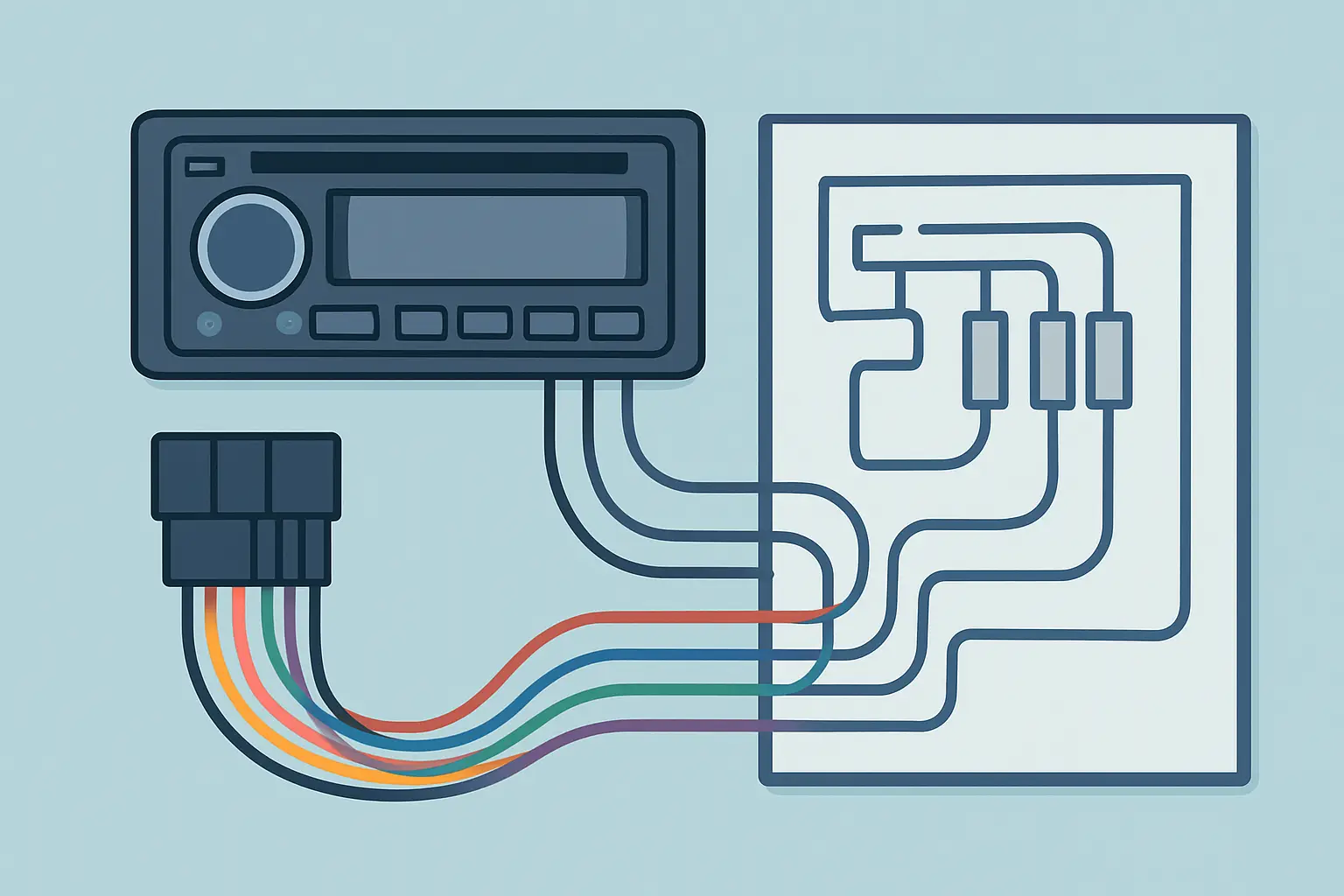
An aftermarket radio wiring diagram is a map of what each wire in the vehicle radio connector does, plus how that connects to the aftermarket radio’s harness. It is the difference between guessing and finishing the job without blown fuses, battery drain, or missing speakers.
On older vehicles, the diagram is mostly about constant power, switched power, ground, illumination, and eight speaker leads. On newer vehicles, the diagram often includes data signals, a separate amplifier turn-on, steering wheel control circuits, and sometimes a factory amp that will not wake up unless it sees the right trigger. That is why “my buddy’s diagram” or a generic chart can be close enough to look right and still be wrong.
Start with the vehicle side, not the radio side
Aftermarket radios are fairly consistent. The vehicle side is not.
The common trap is to wire the aftermarket harness by color code first, then try to make the vehicle match. Instead, treat the vehicle connector as the source of truth and confirm each function. Your diagram should tell you which pin is battery, which is accessory, which is illumination, which is ground, and whether the speakers are direct-wired or routed through a factory amplifier.
If you have two power feeds on the vehicle side, do not assume one is accessory. Some vehicles have a constant feed and a retained accessory power circuit that is controlled by a module. On those, “switched 12V” may not exist at the radio plug at all. It depends on the platform and trim.
Reading the diagram without overthinking it
Most wiring diagrams are easier than they look if you follow the same sequence every time.
Step 1: Identify the connector and pin numbers
A good diagram shows the connector shape, the cavity numbers, and the wire colors. Do not skip the cavity numbers. Wire colors can change between years, trims, or audio packages, and fading or previous repairs can make color unreliable.
If the diagram includes multiple connectors (for example, a main radio plug plus a separate amp plug), note which one you actually have behind the dash. Many “no sound” installs happen because the vehicle has a factory amplifier and the installer only wired the main plug.
Step 2: Separate power and ground from everything else
Before you touch speakers, confirm:
- Battery (constant 12V) is present with the key off.
- Accessory/ignition (switched) behaves the way the diagram says it should.
- Ground is a true ground, not a low-current reference.
A basic multimeter is enough. If the diagram says a wire is constant, it should show battery voltage at all times. If it says switched, it should drop to 0V when the vehicle is off (unless the vehicle uses retained accessory power, which can keep it alive for a period).
If you do not have a reliable switched lead at the radio connector, you may need an interface module or to pull accessory from a proper circuit at the fuse panel. This is one of those “it depends” situations where forcing a workaround can create drain or module issues.
Step 3: Confirm illumination and dimmer behavior
Some vehicles output a simple 12V illumination signal. Others provide a variable dimmer reference, or the lighting is controlled via data. If your diagram shows illumination and dimmer as separate circuits, do not combine them. If the aftermarket radio only has one illumination lead, you may choose to connect illumination only and cap dimmer, or follow the interface recommendation for that vehicle.
Step 4: Determine if speakers are direct or amplified
This is where diagrams pay for themselves.
If the diagram shows speaker pairs leaving the radio connector and going straight to doors, you can wire speaker outputs directly. If the diagram shows low-level signals or an amp input, you need to treat the install differently.
A factory amp system may require:
- An amp turn-on wire (often labeled AMP REM, AMP ON, or similar).
- Using preamp outputs instead of speaker-level outputs.
- Keeping the factory amp and matching its input type, or bypassing it with new speaker wiring.
If you skip the amp turn-on, the radio will “work” but the amp stays asleep, so you get no audio.
The wire functions you should expect to see
Even when colors differ, most installs revolve around the same functions.
Constant power, switched power, and ground
Constant power keeps memory alive. Switched power tells the radio when to turn on. Ground completes the circuit. If any of these are wrong, you get resets, noise, intermittent power, or a dead unit.
Trade-off to consider: some installers tie the radio’s switched lead to constant to “make it turn on.” That can create battery drain and is not a fix. If the vehicle is data-controlled, solve it correctly with the right source or interface.
Speaker pairs
Speakers are typically four pairs: front left, front right, rear left, rear right. The diagram should show positive and negative for each. If your vehicle uses a common ground speaker system (less common on modern vehicles but still seen in some applications), treat that as a stop sign. Many aftermarket radios require floating speaker outputs. You may need a different wiring approach or an interface to avoid damage.
Antenna or amplifier power
Many vehicles need a 12V trigger for the antenna amplifier or powered antenna. If the diagram calls out “antenna amp” or “power antenna,” connect it to the radio’s antenna/remote output, not to constant power.
Steering wheel controls and data lines
If the diagram shows CAN, LIN, or other data circuits at the radio connector, do not probe them randomly and do not connect them to aftermarket wires. Those typically require a steering wheel control interface or a vehicle integration module. The radio might still play audio without them, but features like retained accessory power, chimes, or factory display integration may not.
A practical install workflow that prevents comebacks
A wiring diagram is only useful if you use it the same way every time.
First, bench-prep the aftermarket harness: label constant, accessory, ground, illumination, amp remote, and each speaker pair. Leave extra length so you can service it later.
Next, at the vehicle plug, verify power and ground with the meter and compare to the diagram. If the diagram shows multiple grounds (chassis ground and signal ground), use the one intended for radio power ground.
Then, match each function one at a time. Do not connect speaker outputs until power is stable and the radio boots consistently.
Finally, test with the vehicle running. Some noise issues only show up with the alternator charging. If you get whine, it can be grounding, a factory amp input mismatch, or routing the RCA/speaker wiring alongside power. The diagram helps you confirm you are on the correct circuits before you start chasing symptoms.
Why “universal” diagrams fail
Universal color charts assume the vehicle uses aftermarket color standards. Many vehicles do not. Even within the same make, wire colors and pinouts can change with mid-year updates, premium audio, navigation, or amplified trims.
The other issue is connector variation. Two radios can share the same connector shell while the internal pin assignment changes. Without pin numbers and the correct diagram for the exact year and model, you can connect everything neatly and still land on the wrong cavities.
Getting the right aftermarket radio wiring diagram for your exact vehicle
The fastest route is using a vehicle-specific lookup that filters by Year, Make, Model, and the component you are working on. That matters because “radio” can mean different diagrams: base radio, premium amp, navigation unit, or separate tuner.
If you want a direct, vehicle-filtered way to pull the correct diagram for the exact radio system you are touching, use the Vehicle Selector on Carwiringnew.com and select the radio/audio component that matches your setup.
When the diagram says you need more than wires
Sometimes the diagram confirms you need an interface, not creativity.
If accessory power is data-controlled, you may need a module to generate a clean switched output. If the factory amp expects differential or low-level signals, you may need a line output converter or a harness designed for that amp. If the vehicle routes warning chimes through the radio, removing it without integration can create new problems.
That is not a reason to avoid the job. It is a reason to plan the job so you install once instead of twice.
If you are staring at a dash full of connectors and you are tempted to “try a couple wires,” stop and pull the correct diagram first – it is almost always the cheaper move compared to replacing a fuse block, a radio, or a module you did not mean to wake up.